Week 12: Mechanical Design & Machine Design
This week focuses on designing, building, and automating a low-cost CNC milling machine with a continuity sensor for contour mapping. The project involves mechanical design, manual operation, automation, and documentation of both group and individual contributions.
Introduction
- Group Assignment - Mechanical Design (Part 1): Design a machine that includes mechanism, actuation, automation, and application. Build the mechanical parts and operate it manually. Document the group project.
- Group Assignment - Machine Design (Part 2): Actuate and automate the machine. Document the group project.
- Individual Assignment: Document individual contributions to the group project, highlighting personal roles and tasks.
This week's tasks involve collaborative and individual efforts to create a functional CNC milling machine tailored for educational purposes, emphasizing affordability, modularity, and precision.
Group Assignment
Team: Manuel Ayala-Chauvin, Sandra Nuñez-Torres
Institution: Fablab - Universidad Tecnológica Indoamérica
Year: 2025
Project Overview
This project aimed to design, build, and automate a low-cost CNC milling machine equipped with a continuity sensor to map surface profiles on copper plates. By applying a concurrent engineering approach, the team simultaneously developed the mechanical, electronic, and software systems to achieve a modular, affordable, and replicable machine for educational and research environments.
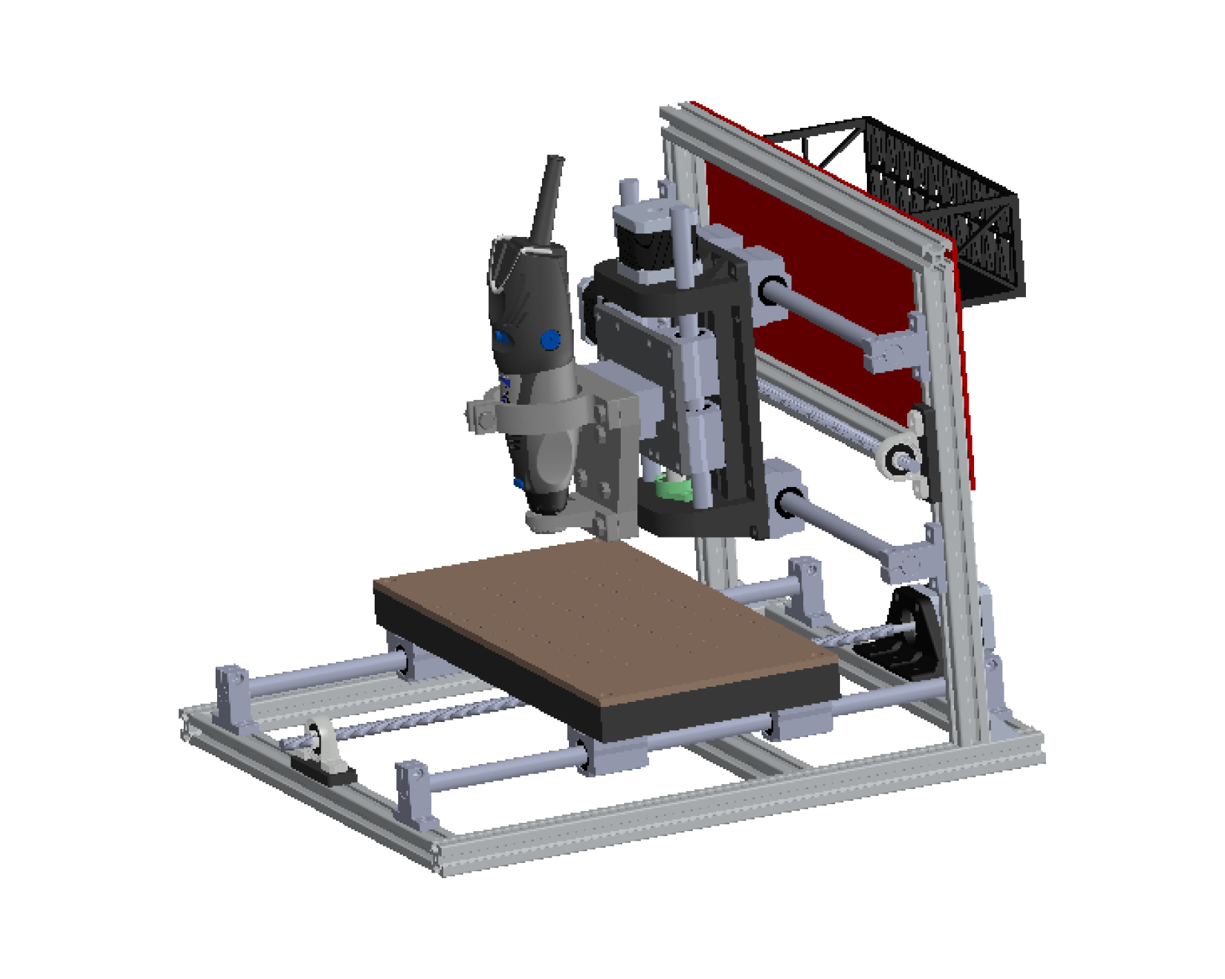
The machine was conceived as a three-axis Cartesian CNC with a leadscrew drive system, capable of manual and automated operation. The design prioritized low-cost materials, ease of fabrication, modularity for future upgrades, and sufficient precision for contour line generation.
Overview of the CNC milling machine structure and components.
Mechanical Design (Part 1) — Group Assignment
Machine Concept
The machine was conceived as a three-axis Cartesian CNC with a leadscrew drive system, capable of manual and automated operation. The design prioritized low-cost materials, ease of fabrication, modularity for future upgrades, and sufficient precision for contour line generation.
Mechanical Design and Manual Testing
The frame was built using aluminum profiles and AISI 1020 steel reinforcements. Movement was guided by linear rails (12 mm) and driven by 8 mm leadscrews with a 2 mm pitch. Before installing electronics, the machine was manually operated via hand cranks to validate mechanical alignment, smoothness of motion, and structural rigidity. FEA simulations predicted a maximum displacement of 0.0236 mm under load, which manual testing later confirmed as acceptable.
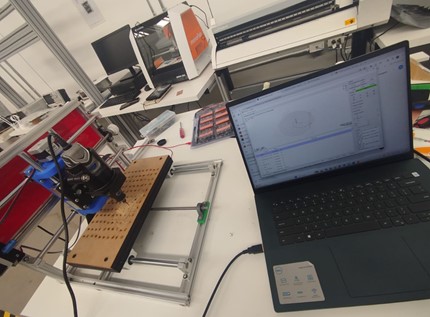
Testing the machine during manual operation to ensure mechanical integrity.
Methodology
The mechanical design was based on a four-stage method:
- Requirements: Define specifications based on cost, flexibility, modularity, and precision.
- Conceptual Design: Modeled in SolidWorks; determined structure, actuation, and materials.
- Detailed Design: Generated CAD files, FEA simulations to validate structure.
- Prototype Fabrication: Built physical structure with aluminum profiles and AISI 1020 steel reinforcements.
The diagram presents the systematic design process used for the low-cost CNC milling machine project. It begins with the identification of technical specifications, which define the project's fundamental requirements such as work area dimensions, desired precision, and operational capacity. The next step involves conceptual design, focusing on selecting suitable motion systems like leadscrews and motors. A bibliographic study of existing CNC technologies is conducted in parallel to enrich the conceptual framework. Once the preliminary design is ready, a technical and economic feasibility study is carried out to evaluate material availability and budget constraints. If materials are not obtainable within the project’s context, the process loops back to redefine specifications and adjust the design accordingly. When feasibility is confirmed, the project advances to the detailed design phase, generating complete CAD models, technical drawings, and part lists. The final stage is the materialization phase, where the prototype is constructed based on the finalized plans. This iterative and feedback-driven process ensures the CNC machine is not only functional and efficient but also economically viable and adaptable to local fabrication capabilities.
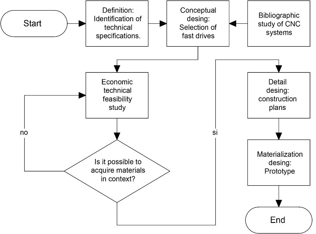
The diagram presents the systematic design process used for the low-cost CNC milling machine project.
Group Collaboration
- Manuel focused on mechanical design, material selection, and manual assembly.
- Sandra designed the usability aspects, including form factor, accessibility, and ergonomic considerations.
Machine Design (Part 2) — Group Assignment
Actuation and Automation
The machine was automated by integrating three NEMA 17 stepper motors driven by DRV8825 drivers, controlled through an Arduino UNO with a CNC Shield. A fine-contact continuity sensor was connected to detect surface variations along the Z-axis. Toolpaths were generated using Vectric Aspire and executed with Universal G-Code Sender.
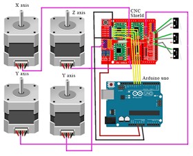
The image illustrates the electronic control system architecture implemented for the CNC milling machine.
Testing after Automation
The automated system was tested over copper plates to verify contour mapping accuracy. Calibration of stepper motor steps/mm and sensor response ensured consistent scanning performance.
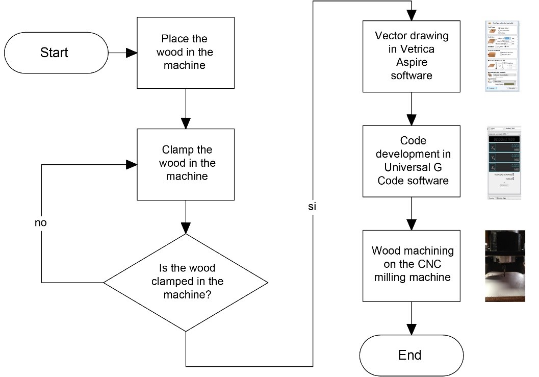
The figure shows the workflow used to machine materials on the CNC milling machine.
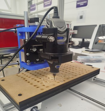
Automated testing of the CNC machine on a copper plate.
Group Collaboration
- Manuel integrated electronics, programmed the Arduino, and developed G-code sequences.
- Sandra focused on usability and safety during automated operations, including layout optimizations for cables and user interface design.
Results and Analysis
Experimental Testing
- 100 surface scans performed on copper plates (100x100 mm).
- Global Mean Error: 4.1%
- Standard Deviation: 0.5%
- Average Scan Time per Piece: 5.8 minutes
Graphical representation of surface scan results.
Video Proof of Operation
Watch the video of operational testing here:
Cost Analysis
| Component | Cost (USD) |
|---|---|
| Stepper Motors (3 units) | $60 |
| Mechanical Components (guides, bearings, leadscrews) | $199 |
| Electronic Components (Arduino, Shield, Drivers) | $198 |
| Spindle (Dremel Tool) | $150 |
| Fabrication Labor and Assembly | $400 |
| Total | $1007 |
Notes: Bulk material sourcing could reduce overall costs by 10-15%.
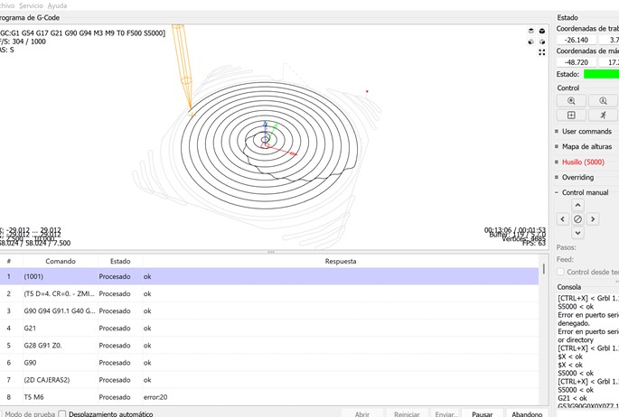
Chart illustrating the cost breakdown of the CNC machine components.
Conclusions
This project successfully demonstrated the viability of designing and constructing a low-cost CNC milling machine for contour mapping applications. Through meticulous mechanical design, careful component selection, and synchronized software development, a highly functional and accessible machine was built.
- Achieved a functional CNC with a total cost of $1007.
- Demonstrated modularity for educational use.
- Maintained precision with a 4.1% mean error in contour mapping.
The collaboration between mechanical design and usability specialists ensured that both technical performance and user experience were addressed from the earliest stages. Future improvements will explore higher resolution sensing, faster scanning speeds, and extended machining capabilities.
© 2025 | Manuel Ayala-Chauvin & Sandra Nuñez Torres | Fab Academy Final Documentation
Individual Assignment
Manuel Ayala-Chauvin
- Developed full SolidWorks CAD models for frame, motion, and assembly systems.
- Performed mechanical dynamic calculations to select actuators.
- Manually fabricated and assembled mechanical systems, aligning and calibrating axes.
- Programmed Arduino firmware for CNC motion and sensor feedback.
- Calibrated stepper motors and continuity sensor for accurate surface scanning.
- Tested full G-code execution cycles and optimized feedrates and acceleration settings.
1. Development of Full SolidWorks CAD Models
As the mechanical design leader, Manuel was responsible for creating detailed three-dimensional CAD models of the entire CNC milling machine using SolidWorks. This work included modeling the primary structure (frames and supports), the motion transmission system (leadscrews, couplings, linear guides), and the mechanical subassemblies (motor mounts, sensor holders, spindle supports). Each component was designed parametrically to allow for easy adjustments and scalability.
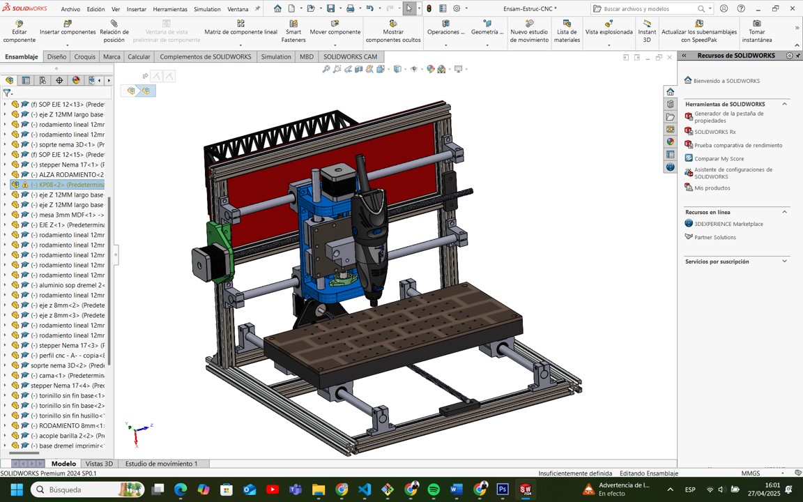
This screenshot shows the complete CAD model of the machine developed in SolidWorks.
2. Performance of Mechanical Dynamic Calculations
Manuel conducted comprehensive mechanical analyses to determine the necessary force and torque requirements for each axis movement. The maximum required force was estimated at 12.45 N, and the corresponding required torque was calculated at 0.00396 Nm. Based on these calculations, NEMA 17 stepper motors (rated at 0.3 Nm torque) were selected.
3. Manual Fabrication and Assembly
After fabrication, Manuel led the mechanical assembly, ensuring careful squaring and alignment of the frame, precision positioning of linear rails, and exact installation of leadscrews and bearings. Mechanical calibration was critical to eliminate friction, misalignment, or backlash.
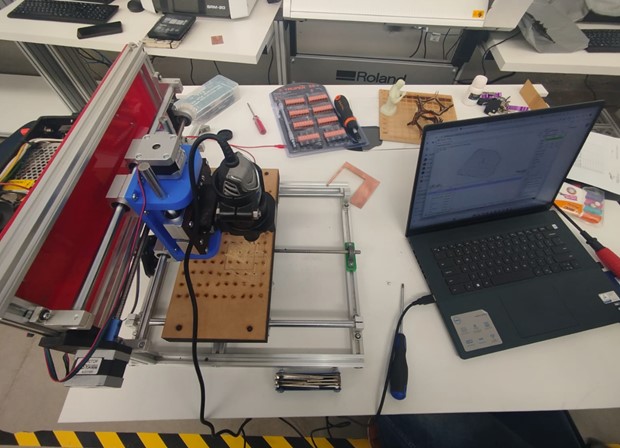
This image displays the fully assembled CNC milling machine ready for operation.
Sandra Nuñez-Torres
- Designed the outer shell, operator interfaces, and panel arrangements.
- Validated user access to key components during manual operation.
- Documented usability testing during early mechanical validation phases.
- Documented usability findings post-automation, suggesting ergonomic improvements.
- Participated in automated testing sessions, ensuring operator safety.
1. Design of the Outer Shell and Interfaces
Sandra designed the external structural elements, including an ergonomic outer shell and operator interfaces like emergency stop locations and control buttons. The red rear protection panel was designed to shield components and manage cables.
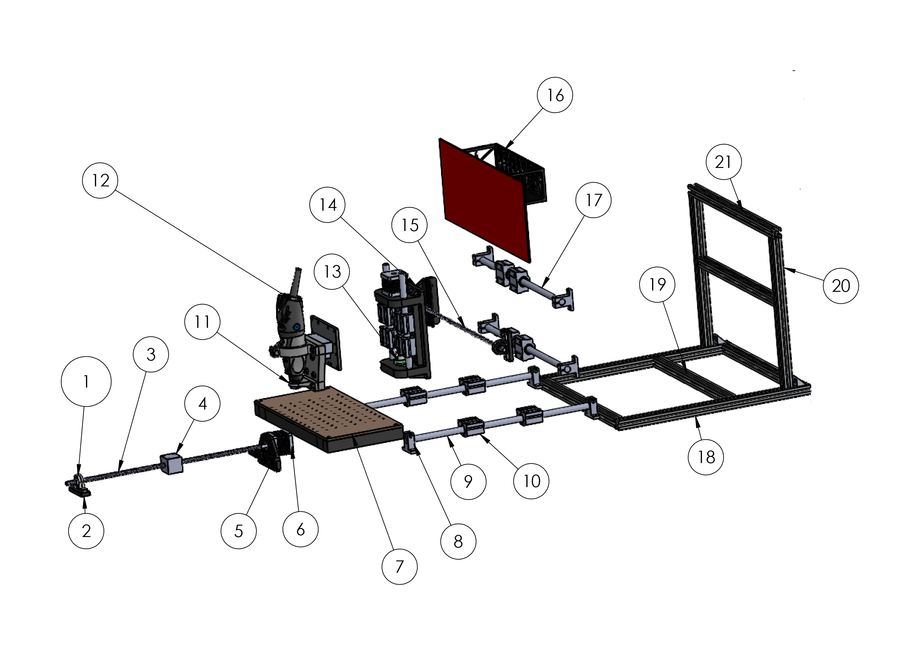
This image shows an exploded view of the CNC milling machine, visualizing component positioning and assembly order.
2. Validation of User Access
Sandra conducted usability inspections to ensure operators could access the spindle head, bed surface, and leadscrew supports comfortably. Adjustments were made to enhance ease of use.
3. Documentation of Usability Testing
Sandra developed a usability testing protocol, documenting ergonomic bottlenecks, safety hazards, and operator fatigue risks. Recommendations included cable routing and protective screens.
Design of the operator interface and control panel for ergonomic use.
Week 12: Conclusion
During Week 12, we successfully applied the complete cycle of mechanical and machine design principles to create a functional, low-cost CNC milling machine capable of surface scanning and material machining. The collaborative effort allowed us to build a robust and replicable system, emphasizing interdisciplinary collaboration and structured design methodologies.
- Successfully integrated mechanical, electronic, and software systems.
- Demonstrated individual expertise in CAD, programming, and usability design.
- Produced a machine suitable for educational environments.
By following concurrent engineering practices, we shortened development time, reduced iteration errors, and achieved a high level of integration across subsystems. This project strengthened our technical and teamwork skills, and we aim to refine the system with higher precision sensors and expanded capabilities.